Welcome back. We have covered the background work as well as deployment parameter sheet in earlier posts. If you missed it, you can find it here…
VMware vCloud Foundation 4.2.1 Step by Step Phase1 – Preparation
VMware vCloud Foundation 4.2.1 Step by Step Phase2 – Cloud Builder & Deployment Parameters
Its time to start the actual deployment. We will resolve the issues as we move on.
Let’s upload the “Deployment Parameter” sheet to Cloud Builder and begin the deployment.
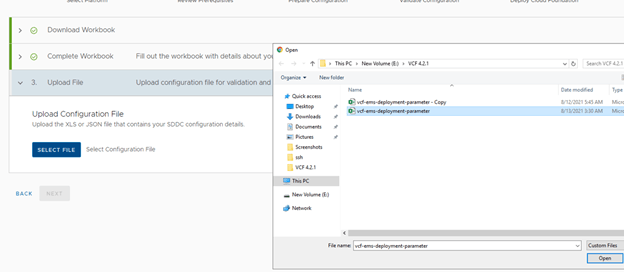
Upload the file and Next. I got an error here.
Bad Request: Invalid input
DNS Domain must match

Figured out to be an additional space in DNS Zone Name here.
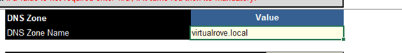
This was corrected. Updated the sheet and NEXT.
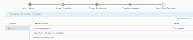
All good. Validation process started.
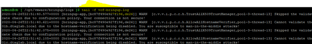
To understand & troubleshoot the issues / failures that we might face while deploying VCF, keep an eye on vcf-bringup.log file. The location of the file is ‘/opt/vmware/bringup/logs/’ in cloud builder. This file will give you live update of the deployment and any errors which caused the deployment to fail. Use ‘tail -f vcf-bringup.log’ to get the latest update on deployment. PFB.
Let’s continue with the deployment…
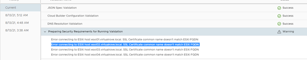
Next Error.
“Error connecting to ESXi host esxi01. SSL Certificate common name doesn’t match ESXi FQDN”
Look at the “vcf-bringup.log” file.

This is because the certificate for an esxi gets generated after it was installed with default name and not when we rename the hostname. You can check the hostname in certificates. Login to an ESXi > Manage> Security & Users> Certificates

You can see here, Even if the hostname on the top shows “esxi01.virtualrove.local, the CN name in certificate is still the “localhost.localdomain”. We must change this to continue.
SSH to the esxi server and run following command to change the hostname, fqdn & to generate new certs.
esxcli system hostname set -H=esxi03
esxcli system hostname set -f=esxi03.virtualrove.local
cd /etc/vmware/ssl
/sbin/generate-certificates
/etc/init.d/hostd restart && /etc/init.d/vpxa restart
Reboot
You need to do this for all hosts by replacing the hostname in the command for each esxi respectively.
Verify the hostname in the cert once server boots up.

Next, Hit retry on cloud builder, and we should be good.

I am not sure why this showed up. I was able to reach to these IP’s from “Cloud Builder”.

Anyways, this was warning, and it can be ignored.
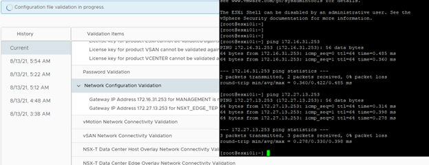
Next one was with host tep and edge tep.

VM Kernel ping from IP ‘172.27.13.2’ (‘NSXT_EDGE_TEP’) from host ‘esxi01.virtualrove.local’ to IP ” (‘NSXT_HOST_OVERLAY’) on host ‘esxi02.virtualrove.local’ failed
VM Kernel ping from IP ” (‘NSXT_HOST_OVERLAY’) from host ‘esxi01.virtualrove.local’ to IP ‘172.27.13.3’ (‘NSXT_EDGE_TEP’) on host ‘esxi02.virtualrove.local’ failed
VM Kernel ping from IP ” (‘NSXT_HOST_OVERLAY’) from host ‘esxi02.virtualrove.local’ to IP ‘172.27.13.2’ (‘NSXT_EDGE_TEP’) on host ‘esxi01.virtualrove.local’ failed
VM Kernel ping from IP ‘172.27.13.3’ (‘NSXT_EDGE_TEP’) from host ‘esxi02.virtualrove.local’ to IP ” (‘NSXT_HOST_OVERLAY’) on host ‘esxi01.virtualrove.local’ failed
VM Kernel ping from IP ‘172.27.13.2’ (‘NSXT_EDGE_TEP’) from host ‘esxi01.virtualrove.local’ to IP ‘169.254.50.254’ (‘NSXT_HOST_OVERLAY’) on host ‘esxi03.virtualrove.local’ failed
VM Kernel ping from IP ” (‘NSXT_HOST_OVERLAY’) from host ‘esxi01.virtualrove.local’ to IP ‘172.27.13.4’ (‘NSXT_EDGE_TEP’) on host ‘esxi03.virtualrove.local’ failed
VM Kernel ping from IP ‘169.254.50.254’ (‘NSXT_HOST_OVERLAY’) from host ‘esxi03.virtualrove.local’ to IP ‘172.27.13.2’ (‘NSXT_EDGE_TEP’) on host ‘esxi01.virtualrove.local’ failed
VM Kernel ping from IP ‘172.27.13.4’ (‘NSXT_EDGE_TEP’) from host ‘esxi03.virtualrove.local’ to IP ” (‘NSXT_HOST_OVERLAY’) on host ‘esxi01.virtualrove.local’ failed
First of all, I failed to understand APIPA 169.254.X.X. We had mentioned VLAN 1634 for Host TEP. It should have picked an ip address 172.16.34.X. This VLAN was already in place on TOR and I was able to ping the GW of it from CB. I took a chance here and ignored it since it was a warning.
Next, got warnings for NTP.
Host cb.virtaulrove.local is not currently synchronising time with NTP Server dc.virtaulrove.local
NTP Server 172.16.31.110 and host cb.virtaulrove.local time drift is not below 30 seconds
Host esxi01.virtaulrove.local is not currently synchronising time with NTP Server dc.virtaulrove.local

For ESXi, Restart of ntpd.service resolved issue.
For CB, I had to sync the time manually.
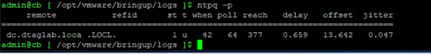
Steps to manually sync NTP…
ntpq -p
systemctl stop ntpd.service
ntpdate 172.16.31.110
Wait for a min and again run this
ntpdate 172.16.31.110
systemctl start ntpd.service
systemctl restart ntpd.service
ntpq -p
verify the offset again. It must be closer to 0.
Next, I locked out root password of Cloud Builder VM due to multiple logon failure. 😊
This is usual since the passwords are complex and sometimes you have to type it manually on the console, and top of that, you don’t even see (in linux) what you are typing.
Anyways, it’s a standard process to reset the root account password for photon OS. Same applies to vCenter. Check the small writeup on it on the below link.
Next, Back to CB, click on “Acknowledge” if you want to ignore the warning.

Next, You will get this window once you resolve all errors.
Click on “Deploy SDDC”.

Important Note: Once you click on “Deploy SDDC”, the bring-up process first builds VSAN on 1st ESXi server from the list and then it deploys vCenter on 1st ESXi host. If bring-up fails for any reason and if you figured out that the one of the parameter in excel sheet is incorrect, then it is tedious job to change the parameter which is already uploaded to CB. You have to use jsongenerator commands to replace the existing excel sheet in the CB. I have not come across such a scenario yet, however there is a good writeup on it from good friend of mine.
Retry Failed Bringup with Modified Input Spec in VCF
So, make sure to fill all correct details in “Deployment Parameter” sheet. 😊
Let the game begin…
Again, keep an eye on vcf-bringup.log file. The location of the file is ‘/opt/vmware/bringup/logs/’ in cloud builder. Use ‘tail -f vcf-bringup.log’ to get the latest update on deployment.
Installation starts. Good luck. Be prepared to see unexpected errors. Don’t loose hopes as there might several errors before the deployment completes. Mine took 1 week to deploy when I did it first time.
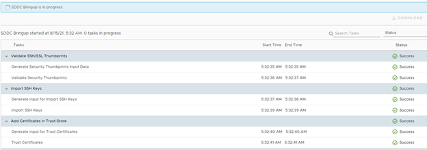
Bring-up process started. All looks good here. Status as “Success”. Let’s keep watching.
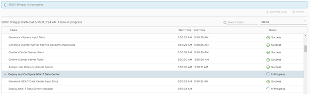
All looks good here. Till this point I had vCenter in place and it was deploying first NSX-T ova.
Looks great.

Glance at the NSX-T env.
Note that the TEP ip’s for host are from the vlan 1634. However, CB validation stage was picking up apipa.
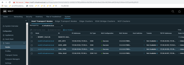
NSX-T was fine. It moved to SDDC further.
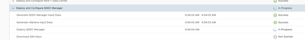
Woo, Bring-up moved to post deployment task.

Moved to AVN (Application Virtual Networking). I am expecting some errors here.

Failed.
“A problem has occurred on the server. Please retry or contact the service provider and provide the reference token. Unable to create logical tier-1 gateway (0)”

This was easy one. vcf-bringup.log showed that it was due to missing DNS record for edge vm. Created DNS record and retry.
Next one,
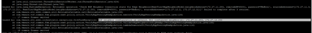
“Failed to validate BGP Neighbor Perring Status for edge node 172.16.31.125”
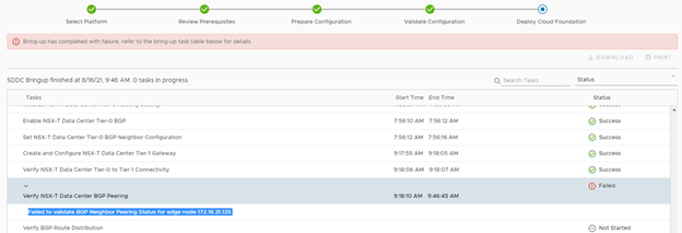
Let’s look at the log file.

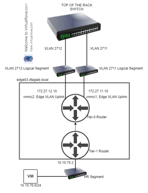
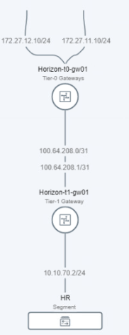
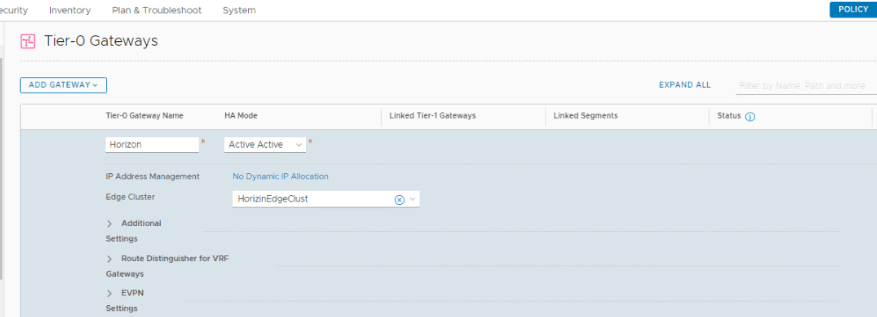
Time to check NSX-T env.
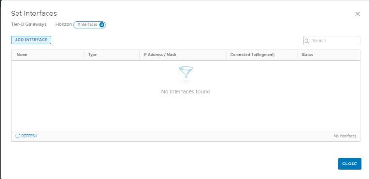
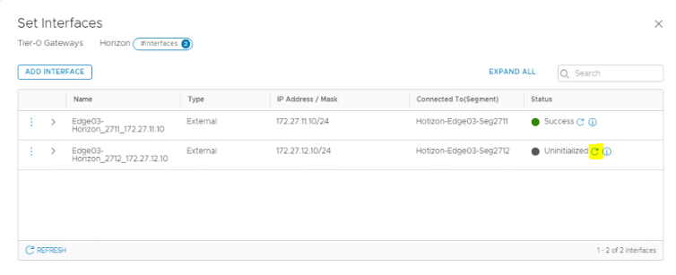
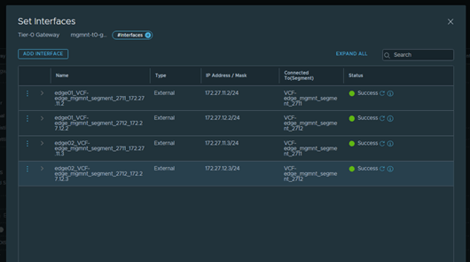
Tier-0 gateway Interfaces looks good as per out deployment parameters.
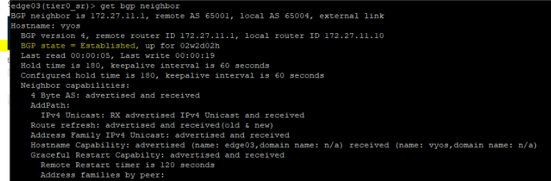
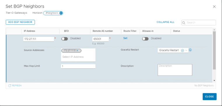
However, BGP Neighbors are down.
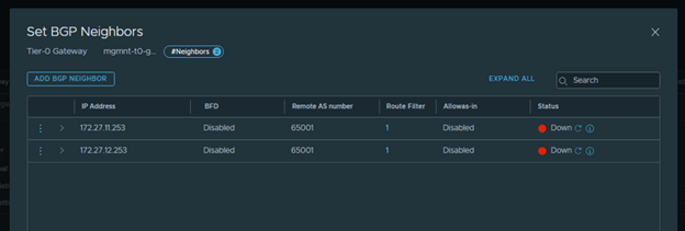
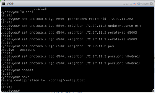
This was expected since we haven’t done the BGP configuration on TOR (VyOS) yet. Let’s get in to VyOS and run some commands.
set protocols bgp 65001 parameters router-id 172.27.11.253
This command specifies the router-ID. If router ID is not specified it will use the highest interface IP address.
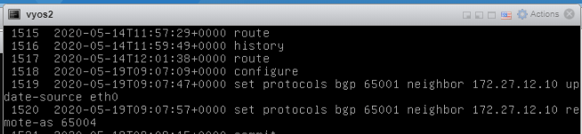
set protocols bgp 65001 neighbor 172.27.11.2 update-source eth4
Specify the IPv4 source address to use for the BGP session to this neighbor, may be specified as either an IPv4 address directly or as an interface name.
set protocols bgp 65001 neighbor 172.27.11.2 remote-as ‘65003’
This command creates a new neighbor whose remote-as is <nasn>. The neighbor address can be an IPv4 address or an IPv6 address or an interface to use for the connection. The command is applicable for peer and peer group.
set protocols bgp 65001 neighbor 172.27.11.3 remote-as ‘65003’
set protocols bgp 65001 neighbor 172.27.11.2 password VMw@re1!
set protocols bgp 65001 neighbor 172.27.11.3 password VMw@re1!
Commit
Save
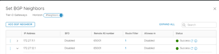
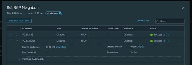
TOR configuration done for 2711 vlan. Let’s refresh and check the bgp status in nsx-t.
Looks good.

Same configuration to be performed for 2nd VLAN. I am using same VyOS for both the vlans since it’s a lab env. Usually, You will have 2 TOR’s and each BGP peer vlan configured respectively for redundancy purpose.
set protocols bgp 65001 parameters router-id 172.27.12.253
set protocols bgp 65001 neighbor 172.27.12.2 update-source eth5
set protocols bgp 65001 neighbor 172.27.12.2 remote-as ‘65003’
set protocols bgp 65001 neighbor 172.27.12.3 remote-as ‘65003’
set protocols bgp 65001 neighbor 172.27.12.2 password VMw@re1!
set protocols bgp 65001 neighbor 172.27.12.3 password VMw@re1!

Both BGP Neighbors are successful.
Hit Retry on CB and it should pass that phase.
Next Error on Cloud Builder: ‘Failed to validate BGP route distribution.’
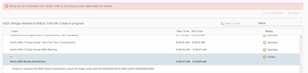
Log File.

At this stage, routing has been configured in your NSX-T environment, both edges have been deployed and BGP peering has been done. If you check bgp peer information on edge as well as VyOS router, it will show ‘established’ and even routes from NSX-T environment appears on your VyOS router. Which means, route redistribution from NSX to VyOS works fine and this error means that there are no routes advertised from VyOS (TOR) to NSX environment. Let’s get into VyOS and run some commands.
set protocols bgp 65001 address-family ipv4-unicast network 172.16.31.0/24
set protocols bgp 65001 address-family ipv4-unicast network 172.16.32.0/24
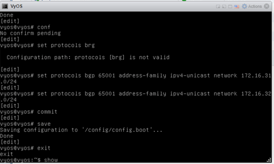
Retry on CB and you should be good.
Everything went smoothly after this. SDDC was deployed successfully.
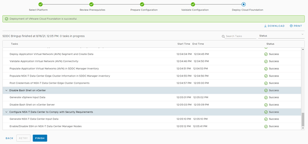
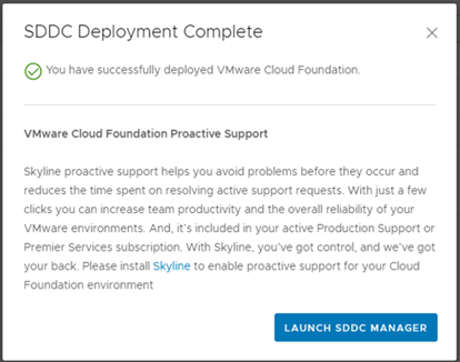
That was fun. We have successfully deployed vCloud Foundation version 4.2.1 including AVN (Application Virtual Networking).
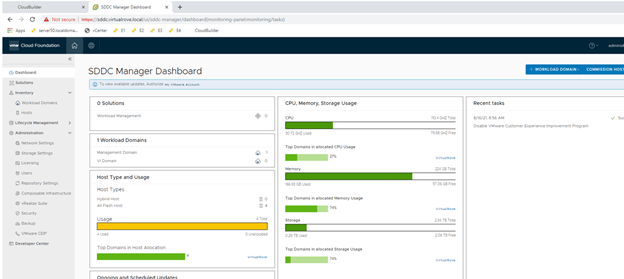
Time to verify and check the components that have been installed.
SDDC Manager.
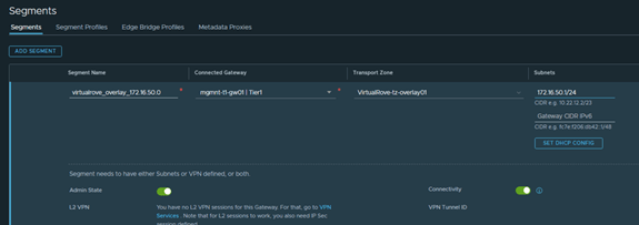
Segments in NSX-T which was specified in deployment parameters sheet.

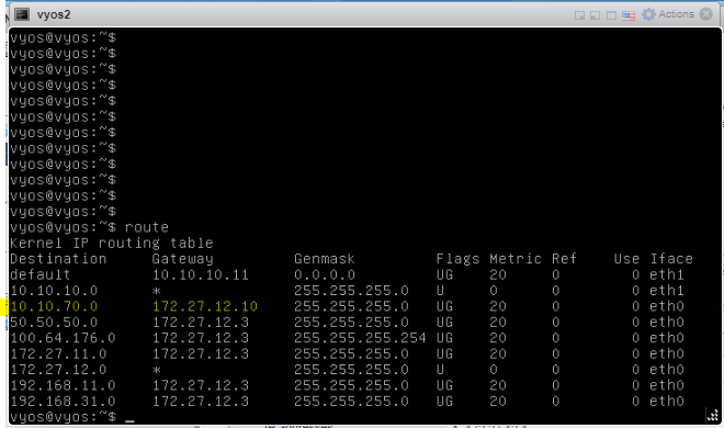
Verify on the TOR (VyOS) if you see these segments as BGP published networks.
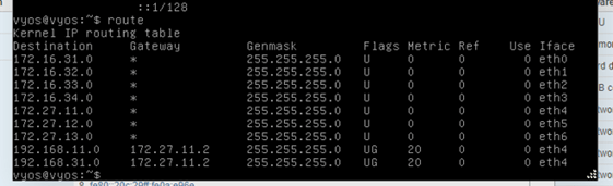
Added a test segment called “virtaulrove_overlay_172.16.50.0” in nsx-t to check if the newly created network gets published to TOR.
All looks good. I see the new segment subnet populated on TOR.

Let’s do some testing. As you see above, new segment subnets are being learned from 172.27.11.2 this interface is configured on edge01 VM. Check it here.

We will take down edge01 VM to see if route learning changes to edge02.
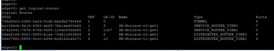
Get into nodes on nsx-t and “Enter NSX Maintenance mode” for edge 01 VM.

Edge01, Tunnels & Status down.

Notice that the gateway address has been failed over to 172.27.11.3.

All Fine, All Good. 😊
There are multiple tests that can be performed to check if the deployed environment is redundant at every level.
Additionally, use this command ‘systemctl restart vcf-bringup’ to pause the deployment when required.
For example, in my case NSX-T manger was taking time to get deployed, and due to an interval on cloud builder, it used to cancel the deployment assuming some failure. So, I paused the deployment after nsx-t ova job got triggered from CB and hit ‘Retry’ after nsx got deployed successfully in vCenter. It picked it up from that point and moved on.
You should have enjoyed reading the post. It’s time for you to get started and deploy VCF. See you in future posts. Feel free to comment below if you face any issues when you deploy the VCF environment.
Are you looking out for a lab to practice VMware products..? If yes, then click here to know more about our Lab-as-a-Service (LaaS).
Leave your email address in the box below to receive notification on my new blogs.