I recently came across a situation where the NSX-T Edge vm in an existing cluster was having issues while loading its parameter. Routing was working fine and there was no outage as such. However, when a customer was trying to select an edge vm and edit it in NSX UI, it was showing an error. Support from VMware said that the edge in question is faulty and needs to be replaced. Again, routing was working perfectly fine.
Let’s get started to replace the faulty edge in the production environment.
Note: If the NSX Edge node to be replaced is not running, the new NSX Edge node can have the same management IP address and TEP IP address. If the NSX Edge node to be replaced is running, the new NSX Edge node must have a different management IP address and TEP IP address.
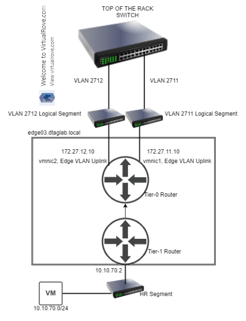
In my lab env, we will replace a running edge. Here is my existing NSX-T env…
Single NSX-T appliance,

All hosts TN have been configured,

Single edge vm (edge 131) attached to edge cluster,

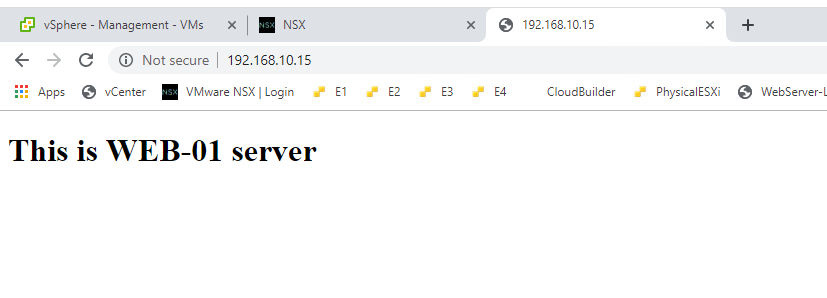
One test workload overlay network. Segment Web-001 (192.168.10.0/24)

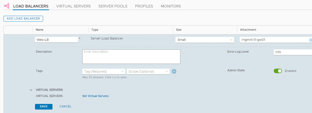
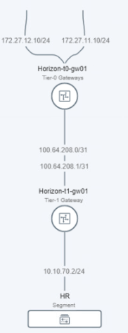
A Tier-0 gateway,

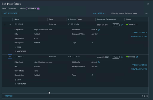
Note that the interfaces are attached to existing edge vm.
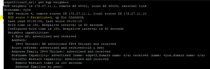
BGP config,

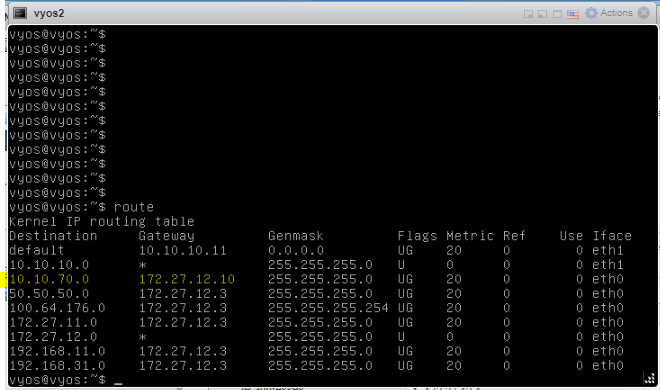
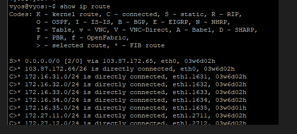
Lastly, my VyOS router showing all NSX BGP routes,

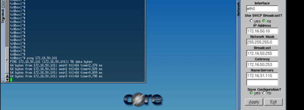
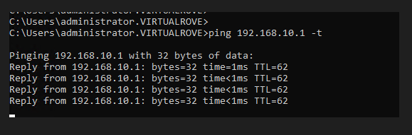
Start continuous ping to NSX test overlay network,
Alright, that is my existing env for this demo.
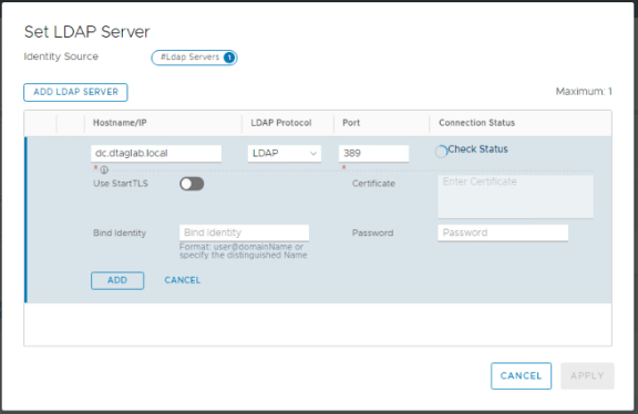
We need one more thing before we start the new edge deployment. The new edge vm parameters should match with the existing edge parameters to be able to replace it. And the existing edge showing an error when we try to open its parameters in NSX UI. The workaround here is to make an API call to existing edge vm and get the configuration.
Please follow the below link to know more about API call.
NSX-T: Edge Transport Node API call
I have copied the output to following txt file,
EdgeApi.txt
Let’s get started to configure the new edge to replace it with existing edge. Here is the link to the blogpost to deploy a standalone edge transport node.
NSX-T: Standalone Edge VM Transport Node deployment
New edge vm (edge132) is deployed and visible in NSX-T UI,

Note that the newly deployed edge (edge132) does not have TEP IP and Edge cluster associated with it. As I mentioned earlier, The new edge vm parameters should match with the existing edge parameters to be able to replace it.
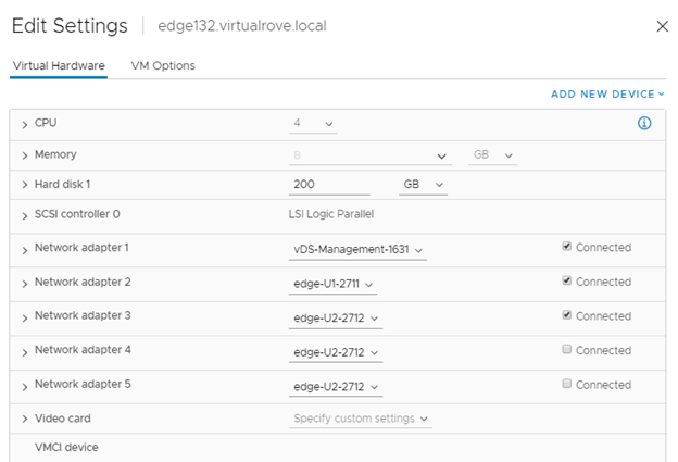
Use the information collected in API call for faulty edge vm and configure the new edge vm the way you see it in the API call. Here is my new edge vm configuration looks like,
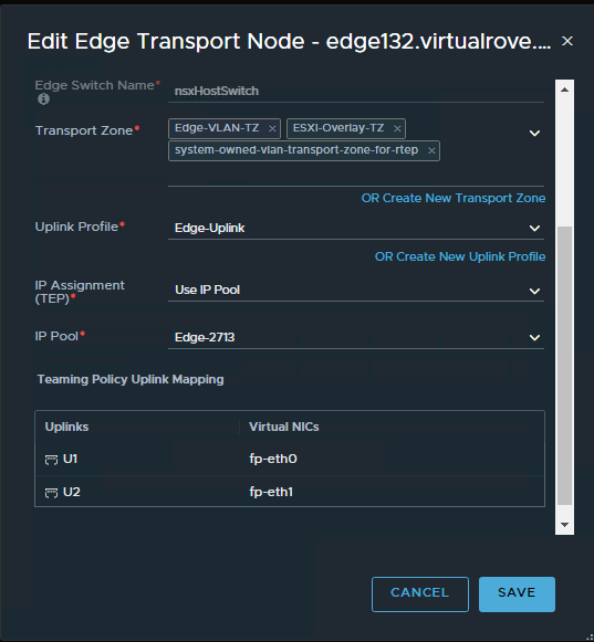
Make sure that the networks matches with the existing non working edge networks.

You should see TEP ip’s once you configure the new edge.
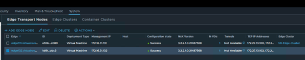
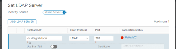
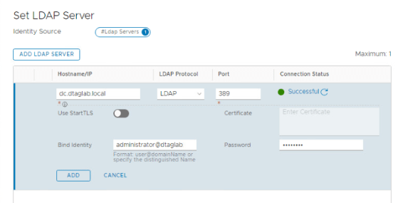
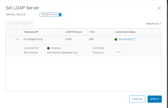
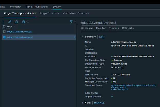
Click on each edge node and verify the information. All parameters should match.
Edge131

Edge132
We are all set to replace the faulty edge now.
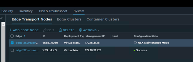
Select the faulty edge (edge131) and click on actions,

Select “Enter NSX Maintenance Mode”

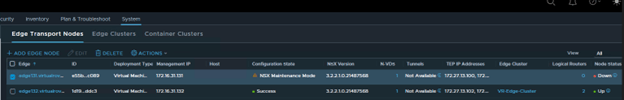
You should see Configuration State as “NSX Maintenance Mode” in the UI.
And you will lose connectivity to your NSX workload.

No BGP route on the TOR
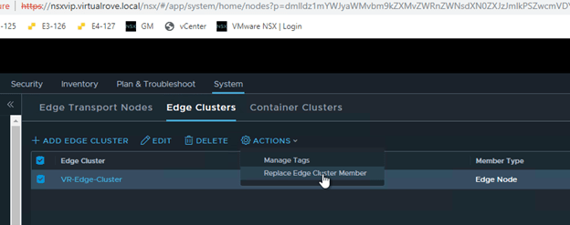
Next, click on “Edge Clusters”, Select the edge cluster and “Action”.
Choose “Replace Edge Cluster Member”
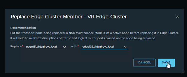
Select appropriate edge vm’s in the wizard and Save,
As soon as the faulty edge have been replaced, you should get the connectivity to workload.

BGP route is back on the TOR.

Interface configuration on the Tier-0 shows new edge node.

Node status for faulty edge shows down,
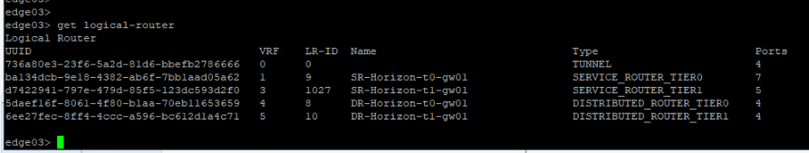
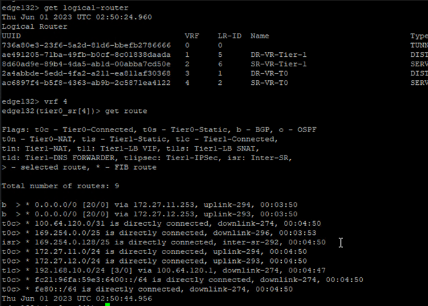
Let’s get into the newly added edge vm and run “get logical-router” cmd,

All service routers and distributed routers have been moved to new edge.
Get into the SR and check routes to make sure that it shows all connected routes too,
We are good to delete the old edge vm.
Lets go back to edge transport node and select the faulty edge and “DELETE”

“Delete in progress”

And its gone.

It should disappear from vCenter too,

Well, that was fun.
That’s all I had to share from my recent experience. There might be several other reasons to replace / delete existing edge vm’s. This process should apply to all those use cases. Thank you for visiting. See you in the next post soon.
Are you looking out for a lab to practice VMware products…? If yes, then click here to know more about our Lab-as-a-Service (LaaS).
Leave your email address in the box below to receive notification on my new blogs.