We have completed NSX-T manager installation in my previous post. Let’s add an additional NSX-T manager for high availability.
Log in to NSX-T manager and navigate to System >Appliances and click on Add Appliance.
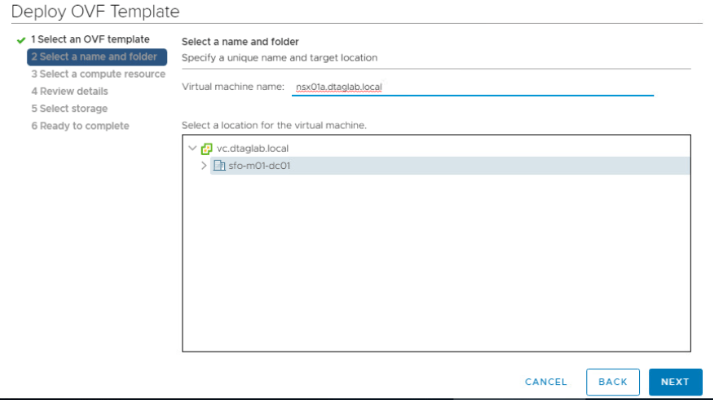
Enter the appliance information. Make sure that the DNS record is created.
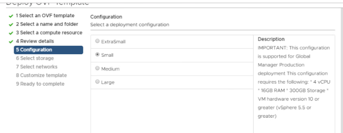
Enter the DNS as well as NTP server. Choose the deployment form factor & click Next.
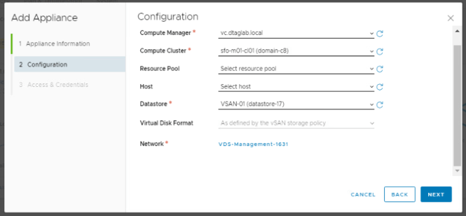
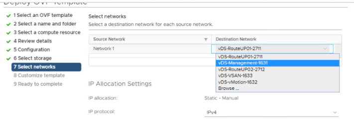
Compute information and network.
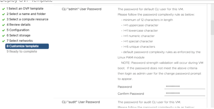
Enable SSH & Root. Enter the password as per the password policy. And install the appliance.
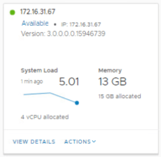
Check the status of the appliance in UI once it is up and running.
Click on View Details and make sure that everything shows UP here.
Follow the same procedure for 3rd (nsx01c.dtaglab.local) appliance.
Next, Set the VIP (Virtual IP) for the cluster. NSX-T Managers Cluster offer a built-in VIP for high availability. The VIP will be connected automatically to the active NSX Manager and rest two will be on stand by.
Enter the IP add >Save.
Create a DNS records for the VIP too.
Check the cluster status. It should show stable with all 3 appliances up and running.
Let’s check it on CLI.
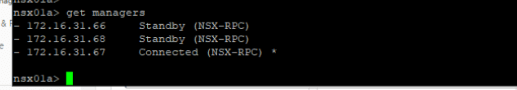
SSH to VIP or any NSX-T manager IP and run few commands.
‘get managers’
‘get cluster config’
All 3 nodes should show up here with the node status as ‘JOINED’
‘get cluster status’
Overall status: Stable
All 3 members status: UP
‘get cluster status verbose’ This command will give you detailed information on each node.
We are done with the NSX-T configuration here. Will move further in my next post. Thank you for checking, I hope it was informational.
VMware NSX-T 3.0 is a newly launched product version of NSX-T. It is highly scalable network virtualization platform. Unlike NSX-V, it can be configured for multi-hypervisor & workloads running in public could. This blog is divided into series of parts, which will help you to successfully install and configure NSX-T 3.0 environment. Like my other blogs, even this blog will focus on practical with limited theoretical information. Here is the VMware official documentation for your reference.
In this post, we will talk about BGP routing configuration required for vCloud Foundation 4.0. In my last post, we deployed vCloud Foundation 4.0 without AVN (Application Virtual Networks). This post includes AVN and its configuration. Application Virtual Networks are logical segments (Logical Switches in NSX-V) that gets created in NSX-T env. These networks can be created manually as per your needs.
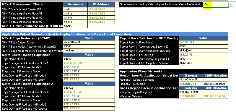
In VCF deployment parameter sheet, you see an option to enable AVN.
If you select ‘NO’, VCF does the deployment of NSX-T managers, Creates VIP & installs NSX-T vibs on esxis, but does not deploy edge and no routing gets configured.
I have selected ‘Yes’ and filled all required parameters in the sheet. We will talk in detail on all these parameters. I have not configured anything on my TOR (top of the rack) yet. We will see errors in deployment and configure it accordingly instead of configuring it beforehand.
Note: VCF does not validate BGP and TOR information in validation process. If you select ‘Yes’ and if something is missing / incorrectly configured, you will see an error in deployment.
With that, lets get started. I selected ‘Yes’ without configuring anything on TOR.
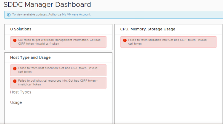
Deployment of SDDC started and showed an error ‘INPUT_PARAM_ERROR Invalid parameter: {0}’ while validating NSX-T Edge parameter. After digging into logs (vcf-bringup.log), I see this…
‘Unexpected edge node form factor: EXTRA_SMALL’
For some reason, it did not like that parameter. The parameter sheet was already uploaded to VCF and it can not be changed once the deployment starts. The only option is to get into respective JSON file and change the values. I did not bother to change the json file. Changed the value deployment parameter to ‘medium’ and restarted the deployment.
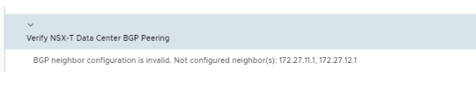
Next Error on Cloud Builder: “BGP neighbor configuration is invalid.”
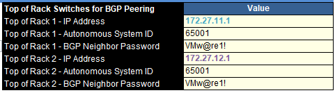
At this stage, it is looking for 2 TOR IP’s for BGP peering. We configured these two IP’s here…
Let’s configure BGP on our VyoS Router. Get into your 1st VyOS router and run these commands.
set interfaces ethernet eth4 address ‘172.27.11.1/24’ set interfaces ethernet eth4 mtu ‘9000’ set protocols bgp 65001 parameters router-id 172.27.11.1 set protocols bgp 65001 neighbor 172.27.11.2 update-source eth4 set protocols bgp 65001 neighbor 172.27.11.2 remote-as ‘65003’ set protocols bgp 65001 neighbor 172.27.11.3 remote-as ‘65003’ set protocols bgp 65001 neighbor 172.27.11.2 password VMw@re1! set protocols bgp 65001 neighbor 172.27.11.3 password VMw@re1!
Checkout my previous blog for more information on VyOS configuration here.
Then get into your 2nd VyOS router and run these commands.
set interfaces ethernet eth0 address 172.27.12.1/24 set interfaces ethernet eth1 mtu ‘9000’ set protocols bgp 65001 parameters router-id 172.27.12.1 set protocols bgp 65001 neighbor 172.27.12.2 update-source eth0 set protocols bgp 65001 neighbor 172.27.12.2 remote-as ‘65003’ set protocols bgp 65001 neighbor 172.27.12.3 remote-as ‘65003’ set protocols bgp 65001 neighbor 172.27.12.2 password VMw@re1! set protocols bgp 65001 neighbor 172.27.12.3 password VMw@re1!
We are done with the BGP configuration on my both routers. Hit retry on cloud builder and you should pass that error.
Keep it mind that we also need to configure inter routing between these two VyOS.
VCF requires 2 TOR (VyOS in our case) to be in place for BGP peer. Let’s discuss about configuring inter-routing between 2 VyOS routers.
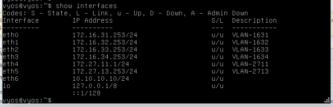
This is how interfaces on VyOS looks like…
VyOS1
Eth4 has the router id (172.27.11.1) which will be used as a 1st BGP peer by NSX-T env.
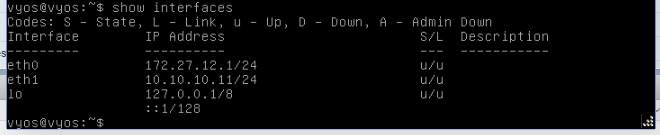
VyOS 2
Eth0 has the router id (172.27.12.1) which will be used as a 2nd BGP peer by NSX-T env.
To enable inter-routing between these two VyOS, I created a port group on my physical esxi called ‘Routable’ and attached both VyOS by adding one more nic card to it. Have a look at eth6 on VyoS 1 and eth1 on VyOS 2. Then added static route enable routing.
I was able to ping all networks of VyOS 1 from VyOS 2 after adding this static route.
We are done with routing at this stage. Lets go back to Cloud Builder and hit retry.
Next Error on Cloud Builder: ‘Failed to validate BGP route distribution.’
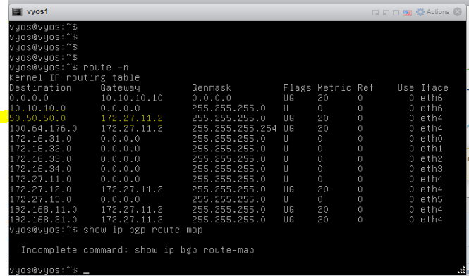
At this stage, routing has been configured in your NSX-T environment, both edges have been deployed and BGP peering has been done. If you check bgp peer information on edge as well as VyOS router, it will show ‘established’ and even routes from NSX-T environment appears on your VyOS router. Which means, route redistribution from NSX to VyOS works fine and this error means that there are no routes advertised from VyOS (TOR) to NSX environment. Let’s get into VyOS and run some commands.
set protocols bgp 65001 address-family ipv4-unicast network 172.16.31.0/24 set protocols bgp 65001 address-family ipv4-unicast network 172.16.32.0/24
I have advertised 1631 & 1632 vlan from VyoS to BGP 65001 network. Your network admin will decide on which networks to be published/advertised to NSX-T env.
And we are done..!!!
vCloud Foundation 4.0 with AVN has been installed and configured successfully.
To test the routing, I created a segment in NSX-T environment called ‘Accounts’ & CIDR as ’50.50.50.50/24’. I see this network populated on my TOR (VyOS router)
That’s it for this post. In my next post, we will deploy NSX-T edges and configure routing manually to get more understanding of the BGP routing in NSX-T environment.
In this post, we will perform step by step installation of vCloud Foundation 4.0. It has been couple of weeks since this version has released. I have been working on VCF & VVD since couple of years and deployed it multiple times, hence wanted to write a blog on it.
Before we start with VCF 4.0, Please check the network configuration in my VyOS Virtual Router blog here.
Introduction:
VMware Cloud Foundation is a private as well as public cloud solution. It is a unified platform which will give you entire SDDC stack. VCF 4.0 includes vSphere 7.0, VSAN 7.0, NSX-T 3.0, VRA 8.1 as well as SDDC manager to manage your virtual infrastructure domains. One more big change in VCF 4.0 is, Kubernetes Cluster deployment through SDDC manager after successful deployment of management domain.
Bills of material (Image copied from VMware site)
Check out VMware’s official site for all new features & release notes here…
vCloud Foundation deployment requires multiple networks to be in place before we start the deployment. We will discuss about the network requirements for successful deployment.
Network Requirements: Following management domain networks to be in place on physical switch (TOR). Jumbo frames (MTU 9000) are recommended on all VLANs or minimum of 1600 MTU. Check out the ports requirements on VMware site https://ports.vmware.com/home/VMware-Cloud-Foundation
Follow my previous blog for network configuration here.
Physical Hardware: Minimum 4 physical server with preinstalled VMware ESXi 7.0 hypervisor for VSAN cluster.
AD & DNS Requirements: Active Directory (Domain Controller) to be in place. In our case, DC is connected to 1631 VLAN on VyOS. Following DNS records to be in place before we start with the installation.
Pre-installed ESXi Configuration:
All ESXi must have ‘VM network’ and ‘Management network’ VLAN id 1631 configured. NTP server address should be in place on all ESXi. SSH & NTP service to be enabled and policy set to ‘Start & Stop with the host’ All additional disks to be present on an ESXi for VSAN configuration.
Let’s begin with the nested ESXi configuration for our lab.
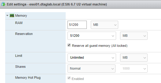
Create 4 new VM’s on physical ESXi. These will be our nested ESXi where our VCF env will get install. All ESXi should have identical configuration. I have following configuration in my lab.
CPU: 16 CPU hot plug: Enabled Hardware Virtualization: Enabled
Once done, run ‘esxcli storage core device list’ command and verify if you see SSD instead of HDD.
This completes our ESXi configuration.
Cloud Builder:
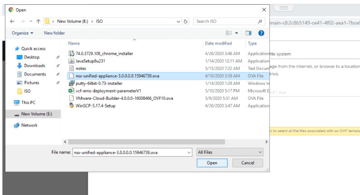
Cloud Builder is an appliance provided by VMware to build VCF env on target ESXi’s. It is one time use VM and can be powered off after the successful deployment of VCF management domain. After deployment, we will use SDDC manager for managing additional VI domains. I will be deploying this appliance in VLAN 1631, so that it gets access to DC and all our ESXi servers. Download the CB appliance from VMware downloads.
Deployment is straight forward like any other ova deployment. Make sure to you choose right password while deploying the ova. The admin & root password must be a minimum of 8 characters and include at least one uppercase, one lowercase, one digit, and one special character. If this does not meet, then the deployment will fail which results in re-deploying ova.
Till now, we have completed configuration of Domain controller, VyoS router, nested ESXi & Cloud Builder ova deployment. Following VM’s have been created on my physical ESXi host.
Log into Cloud Builder using configured fqdn and click next on this screen.
Check if all prereqs are in place and click Next.
Download the ‘Deployment Parameter Workbook’ on this page.
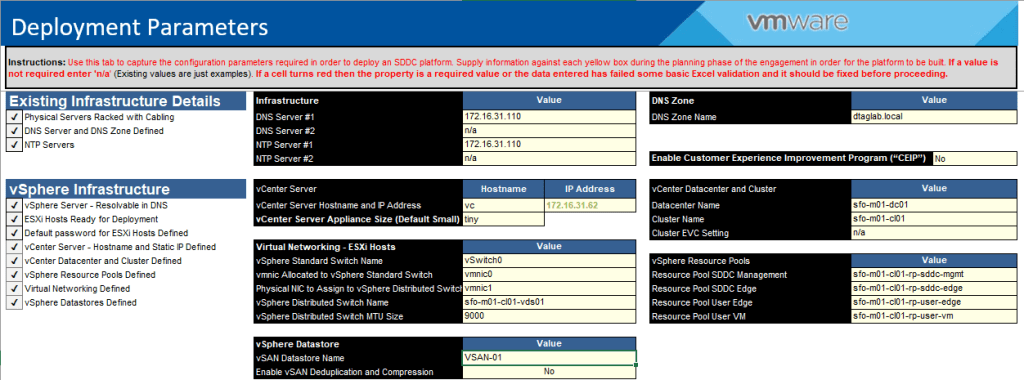
Deployment Parameter Workbook:
It is an Excel sheet which needs to be filled accurately without breaking its format. Be careful while filling this workbook, as it provides all input parameters for our VCF deployment. Let’s have a look at the sheet.
Prerequisite Checklist: Cross check your environment as per prereqs.
Management Workloads: All license information needs to go in here.
Users and Groups: You need specify all passwords here. Check out the NSX-T passwords, as the validation fails if it does not match the password policy.
Hosts and Networks: Edit network information as per the environment and update ESXi information accordingly.
Deploy Parameters: Fill out all the information as per your environment. If you miss something, the cell turns red which causes failure in validation.
After you complete this sheet, it needs to be uploaded in cloud builder on this page.
Next is, Validation of the workbook and preinstalled ESXi.
Resolve any errors / warnings that shows up here.
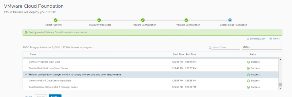
Status should show ‘Success’ for all validation items. Click Next and click on Deploy SDDC.
All SDDC components gets installed on nested ESXi and you see this message.
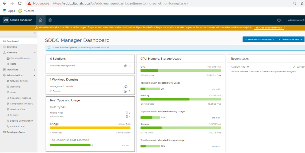
SDDC Deployment Complete.
Check the SDDC Manager and vCenter.
It was defiantly not that easy for me first time. This was my 3rd deployment which got successful in 1st run. The last successful run took around 4 hours to complete. I have written this blog after resolving the errors that I got, so that you don’t waste time in troubleshooting. If you miss any steps in this post, you will surely end up in errors.
Here are some suggestions.
Keep checking vcf-bringup.log in cloud builder for any errors in deployment. The location of the file is ‘/opt/vmware/bringup/logs/’ in cloud builder. This file will give you live update of the deployment and any errors which caused the deployment to fail. Use ‘tail -f vcf-bringup.log’ to get the latest update on deployment. PFB.
Another error ‘The manifest is present but user flag causing to skip it.’ caused my deployment to fail.
To resolve this, I changed the deployment model of NSX-T to ‘Small’ from ‘Medium’. Looked like it was compute resource issue.
Also, keep checking NTP sync on the cloud builder. Mine did not sync with NTP for some reason and I had to manually sync it.
Steps to manually sync NTP… ntpq -p systemctl stop ntpd.service ntpdate 172.16.31.110 Wait for a min and again run this ntpdate 172.16.31.110 systemctl start ntpd.service systemctl restart ntpd.service ntpq -p
Verify the offset again. It must be closer to 0.
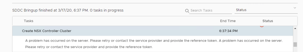
NSX-T Deployment error.
The NSX-T OVF wasn’t getting installed. I could see generic error in vCenter. Reboot of entire environment fixed the issue for me.
Also, use this command ‘systemctl restart vcf-bringup’ to pause the deployment when required.
For example, my NSX-T manger was taking time to get deployed, and due to an interval on cloud builder, it used to cancel the deployment assuming some failure. So, I paused the deployment after nsx-t ova job got triggered from CB and hit ‘Retry’ after nsx got deployed successfully in vCenter. It picked it up from that point and moved on.
That’s it for this post. I will come up with some more posts on VCF 4.0. Next is to deploy additional workload domain and application networks for it.
Configure and Install VyOS virtual router for vSphere Lab
To successfully build and test functionalities / features of VMware vSphere, we need following networks in place. This will enable you to test features like vMotion, High Availability & VSAN.
Management Network vMotion Network VSAN Network Uplink Network for North South communication
Since we do not have physical router to connect to, we will use VyOS open source router. This router will act as a TOR for our vSphere environment. In this blog, we will discuss step by step VyOS open source router configuration for VMware lab. This router will be used in all my VMware labs. To start with, I have a single physical ESXi host with following configuration…
By default, An ESXi will have standard vSwitch0 with VM & Management Network port groups. No need to make any changes here. Create one more standard switch name ‘VyOS’ with NO uplink.
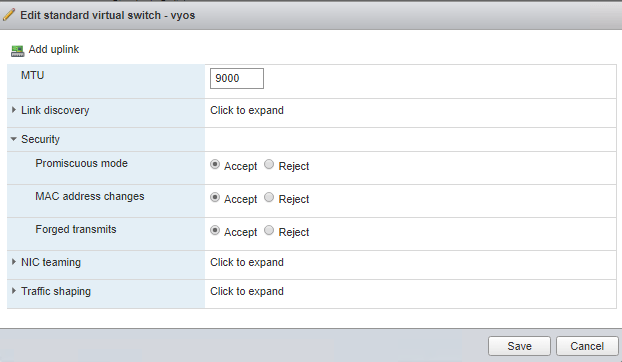
Edit switch properties as follows…
Promiscuous Mode – Accept MAC change – Accept Forged Transmits – Accept MTU can remain 1500 or can be changed as per your requirement.
Checkout VMware documentation for more information on switch properties.
Next step is to create VM port groups on newly created standard switch. The number of port groups will depend on the number of networks you want in nested lab. I wanted to build this lab vCloud Foundation, hence I created following port groups on VyOS router.
This is how it looks in physical ESXi.
One additional network called “Trunk” with VLAN ID 4095. This will act as a trunk port for all my nested ESXi hosts. A VLAN ID of 4095 represents all trunked VLANs. This will allow all VLAN traffic to and from nested ESXi.
At this stage, we are ready to install and configure VyOS router. Download VyOS router ISO from https://downloads.VyOS.io/ OR from any other trusted sources.
Installing VyOS is straight forward like you create any other VM on an ESXi. Create a VM- Name – OS Type – Storage Type- Attach ISO.
For networks, we need to add multiple network interfaces according to number of networks we want in our nested lab environment. Here is how it looks like after adding multiple interfaces. We don’t need to add interface for Trunk port group here, since it will be used by our ESXi severs.
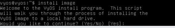
Power On the VM and open console for further configuration. Login with default user name “VyOS” and default password “VyOS”.
Install image on local disk so that we don’t loose the configuration upon reboot.
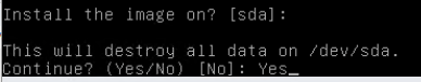
Type Yes
Type Auto and continue
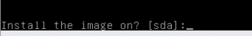
Install image on SDA.
Type Yes & Hit Enter for default size option to start the installation.
Name the router and hit enter for Copy option.
Enter the new password for this router and default boot partition.
Installation complete. Power off the VM.
Detach the VyOS ISO from the VM and power it on again. Log in with new credentials and we are good to configure the router.
Check the interfaces on the router. “show interfaces”
This will be equal to network interfaces that you added while creating a VM. We need to configure these interfaces.
Note: VyOS starts routing between all connected interfaces as soon as you configure them. There is no need of any additional configuration.
Get into configuration mode using ‘config’ command and set your interfaces.
set interfaces ethernet eth0 address 172.16.31.253/24 set interfaces ethernet eth1 address 172.16.32.253/24 set interfaces ethernet eth2 address 172.16.33.253/24 set interfaces ethernet eth3 address 172.16.34.253/24 set interfaces ethernet eth4 address 172.27.11.253/24 set interfaces ethernet eth5 address 172.27.12.253/24 set interfaces ethernet eth6 address 172.27.13.253/24
Set the description and & MTU of the interface.
set interfaces ethernet eth0 description VLAN-1631 set interfaces ethernet eth1 description VLAN-1632 set interfaces ethernet eth2 description VLAN-1633 set interfaces ethernet eth3 description VLAN-1634 set interfaces ethernet eth4 description VLAN-2711 set interfaces ethernet eth5 description VLAN-2712 set interfaces ethernet eth6 description VLAN-2713
set interfaces ethernet eth0 mtu 9000 set interfaces ethernet eth1 mtu 9000 set interfaces ethernet eth2 mtu 9000 set interfaces ethernet eth3 mtu 9000 set interfaces ethernet eth4 mtu 9000 set interfaces ethernet eth5 mtu 9000 set interfaces ethernet eth6 mtu 9000
Make sure to commit and save the configuration.
Check interfaces after configuration.
We have configured 7 networks here and .253 will act as a gateway in respective subnet in our nested environment. We are done with the basic configuration of the router here. This router will act as a TOR for our vSphere Environment.
Additional configuration needed for Internet Access in these networks…
Add one more network interface to VyOS (eth7), this interface will be connected to the ‘VM Network’ on ‘vSwitch0’ and NOT on the additional switch that we created. I will assign “151.100.100.100/29” network to eth7, since my physical ESXi is configured with this network and it has internet connectivity. And “151.100.100.233” as a gateway, since it is a gateway of my ISP as well as my physical ESXi.
Steps to configure on VyOS…
configure set interfaces ethernet eth7 address 151.100.100.100/29 set interfaces ethernet eth7 description Internet commit save set protocols static route 0.0.0.0/0 next-hop 151.100.100.233 distance 1 commit save set nat source rule 101 outbound-interface eth7 set nat source rule 101 source address ‘172.16.31.0/24’ set nat source rule 101 translation address masquerade commit save
This will enable internet access for all VM’s that gets connected to 172.16.31.0 network.
I will post more configuration commands in my upcoming posts. I hope this was helpful for you. Feel free to post comments if you find any difficulties in configuration.