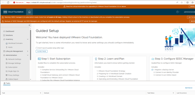
It’s time to check VCF environment and do some post checks. Here is the SDDC manager after the deployment,
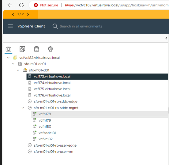
Host & Clusters view,
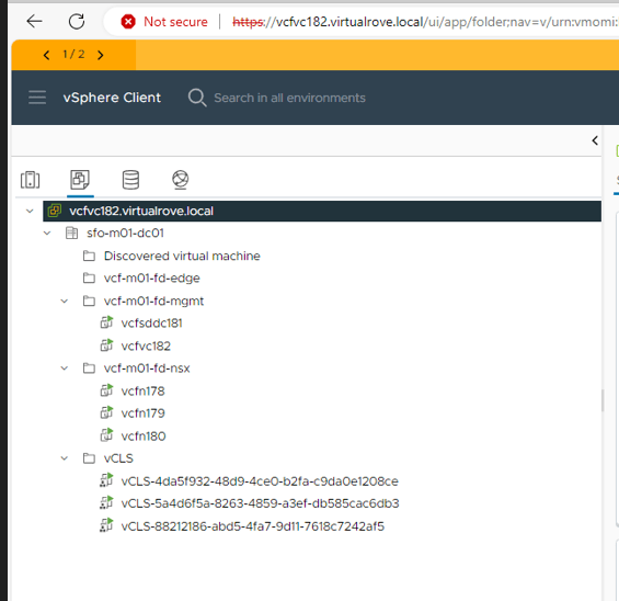
VM’s & Templates,
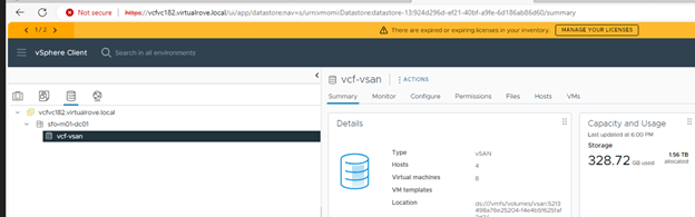
Datastore,
And Networking,
Let’s look at the NSX env,
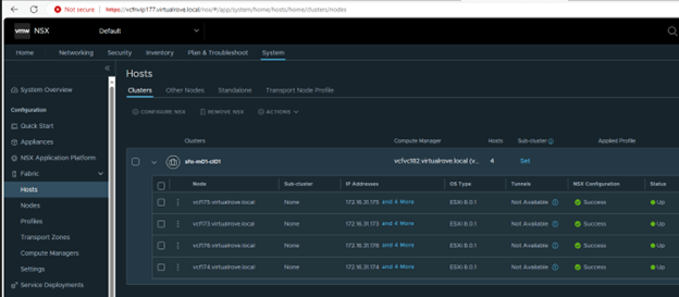
All management hosts have been prepared for nsx,
Host configuration on one of the host in this cluster, “vcf-vds01” configured for NSX. TZ, Uplink profile & IP pool created and configured already.
vCenter Virtual switch view on one of the host,
NSX already have backup configured, And the last backup was successful.
If you look at the backup config, it has configured sddc as a backup server,
Lets have a look at the SDDC manager dashboard,
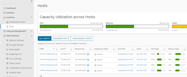
Host view on SDDC shows as expected,
Workload Domain view shows our management domain,
Click on the management domain name to check details,
Host tab on under the management domain shows host details again,
Edge clusters are empty. You get an option to deploy edge clusters for mgmnt domain. I will be writing separate blog on it,
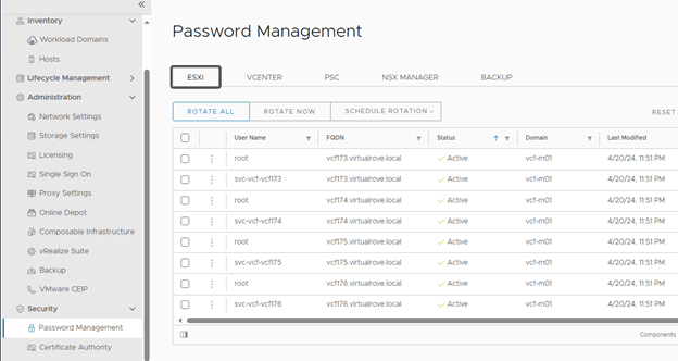
Password management options allows you to create / edit passwords for all SDDC components at one place. You can also schedule password rotation for all components.
As discussed in the first blog of this series, here is the option to subscribe to licenses,
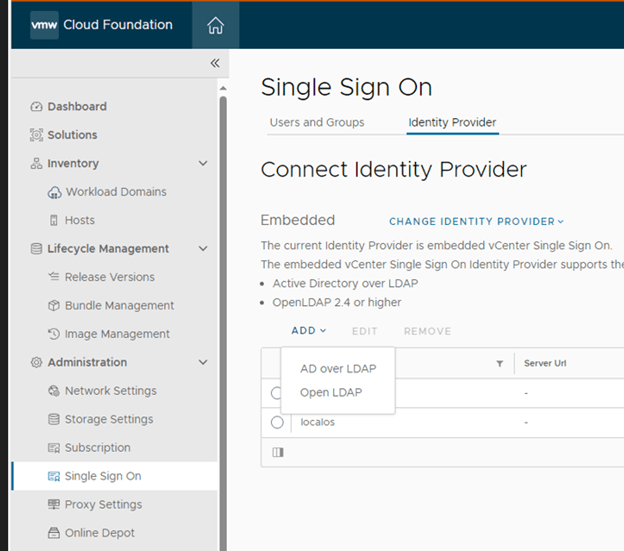
Like other products of VMware, you get an option to integrate AD,
Option to deploy vRealize Suite from SDDC,
Well, that’s all for this post. Keep following for upcoming blogs on VCF 5.X.
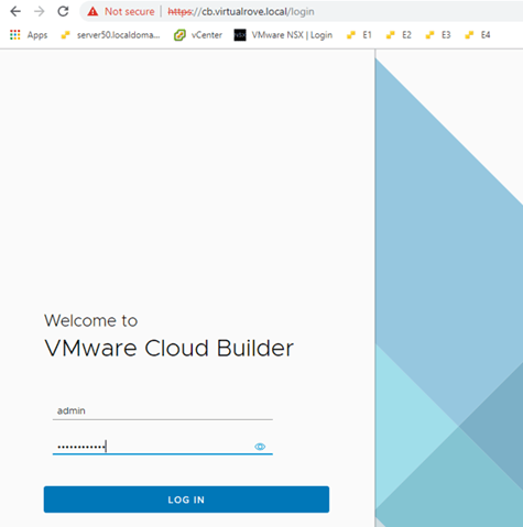
Login to Cloud Builder VM and start the deployment process.
Select “vCloud Foundation” here,
The other option “Dell EMC VxRail” to be used when your physical hardware vendor is Dell.
VxRail is hyper-converged appliance. It’s a single device which includes compute, storage, networking and virtualization resources. It comes with pre-configured vCenter and esxi servers. Then there is a manual process to convert this embedded vCenter into user manage vCenter, and that’s when we use this option.
Read all prereqs on this page and make sure to fulfill them before you proceed.
Scroll down to check remaining prereqs,
Click next here.
Earlier versions of VCF gave an option to download the “Deployment Parameter” excel sheet on this page.
You must download this sheet from the same place where you downloaded the vcf ova from.
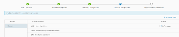
Its time to start the actual deployment. We will resolve the issues as we move on. Let’s upload the “Deployment Parameter” sheet to Cloud Builder and begin the deployment.
Upload the file and Next. CB validates everything that is required for the complete deployment in this step.
To understand & troubleshoot the issues / failures that we might face while deploying VCF, keep an eye on vcf-bringup.log file. The location of the file is ‘/opt/vmware/bringup/logs/’ in cloud builder. This file will give you live update of the deployment and any errors which caused the deployment to fail. Use ‘tail -f vcf-bringup.log’ to get the latest update on deployment. PFB.
Let’s continue with the deployment…
“Error connecting to ESXi host. SSL Certificate common name doesn’t match ESXi FQDN”
Look at the “vcf-bringup.log” file.
This is because the certificate for an esxi gets generated after it was installed with default name and not when we rename the hostname. You can check the hostname in certificates. Login to an ESXi > Manage> Security & Users> Certificates
You can see here, Even if the hostname on the top shows “vcf157.virtualrove.local, the CN name in certificate is still the “localhost.localdomain”. We must change this to continue.
SSH to the esxi server and run following command to change the hostname, fqdn & to generate new certs.
esxcli system hostname set -H=vcf157 esxcli system hostname set -f= vcf157.virtualrove.local cd /etc/vmware/ssl /sbin/generate-certificates /etc/init.d/hostd restart && /etc/init.d/vpxa restart Reboot
You need to do this for all hosts by replacing the hostname in the command for each esxi respectively.
Verify the hostname in the cert once server boots up.
Next, Hit retry on cloud builder, and we should be good.
Next, warning for vSAN Disk Availability Validate ESXi host has at least one valid boot disk.
Not sure about this one. Double checked and confirm that all disks are available on the esxi host. I will simply ignore this.
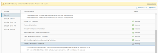
Next, warnings for NTP. Host cb.virtaulrove.local is not currently synchronising time with NTP Server dc.virtaulrove.local NTP Server 172.16.31.110 and host cb.virtaulrove.local time drift is not below 30 seconds
For ESXi, Restart of ntpd.service resolved issue. For CB, I had to sync the time manually.
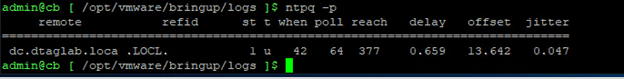
Steps to manually sync NTP… ntpq -p systemctl stop ntpd.service ntpdate 172.16.31.110 Wait for a min and again run this ntpdate 172.16.31.110 systemctl start ntpd.service systemctl restart ntpd.service ntpq -p
verify the offset again. It must be closer to 0. Next, I locked out root password of Cloud Builder VM due to multiple logon failure. 😊
This is usual since the passwords are complex and sometimes you have to type it manually on the console, and top of that, you don’t even see (in linux) what you are typing.
Anyways, it’s a standard process to reset the root account password for photon OS. Same applies to vCenter. Check the small writeup on it on the below link.
Next, Back to CB, click on “Acknowledge” if you want to ignore the warning.
Next, You will get this window once you resolve all errors. Click on “Deploy SDDC”.
Important Note: Once you click on “Deploy SDDC”, the bring-up process first builds VSAN on 1st ESXi server from the list and then it deploys vCenter on 1st ESXi host. If bring-up fails for any reason and if you figured out that the one of the parameter in excel sheet is incorrect, then it is tedious job to change the parameter which is already uploaded to CB. You have to use jsongenerator commands to replace the existing excel sheet in the CB. I have not come across such a scenario yet, however there is a good writeup on it from good friend of mine.
So, make sure to fill all correct details in “Deployment Parameter” sheet. 😊
Let the game begin…
Again, keep an eye on vcf-bringup.log file. The location of the file is ‘/opt/vmware/bringup/logs/’ in cloud builder. Use ‘tail -f vcf-bringup.log’ to get the latest update on deployment.
Installation starts. Good luck. Be prepared to see unexpected errors. Don’t loose hopes as there might several errors before the deployment completes. Mine took 1 week to deploy when I did it first time.
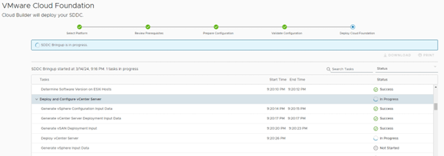
Bring-up process started. All looks good here. Status as “Success”. Let’s keep watching.
It started the vCenter deployment on 1st VSAN enabled host.
You can also login to 1st esxi and check the progress of vCenter deployment.
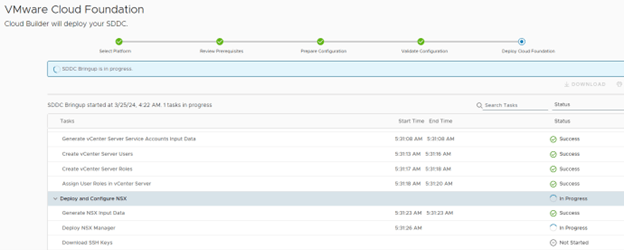
vCenter installation finished. Moved to NSX deployment.
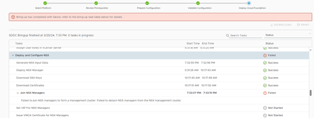
Failed at NSX deployment stage,
Failed to join NSX managers to form a management cluster. Failed to detach NSX managers from the NSX management cluster.
I logged into the all 3 NSX managers and found that one of the NSX manager were showing Management UI: DOWN on the console. Restarted the affected NSX manager and it was all good.
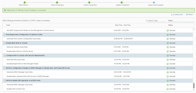
Retry on the CB did not show that error again. And finally, it finished all tasks.
Click Finish. And it launches another box.
That was fun. We have successfully deployed vCloud Foundation version 5.0
There are multiple tests that can be performed to check if the deployed environment is redundant at every level. Time to verify and do some post deployment checks. I will cover that in next post.
Additionally, use this command ‘systemctl restart vcf-bringup’ to pause the deployment when required.
For example, in my case NSX-T manger was taking time to get deployed, and due to an interval on cloud builder, it used to cancel the deployment assuming some failure. So, I paused the deployment after nsx-t ova job got triggered from CB and hit ‘Retry’ after nsx got deployed successfully in vCenter. It picked it up from that point and moved on.
Hope you enjoyed reading the post. It’s time for you to get started and deploy VCF. Feel free to comment below if you face any issues.
We have prepared the environment for VCF deployment. Its time to discuss the “Deployment Parameters” excel sheet in detail. Following are lists of blogs in this series.
“Introduction” sheet from the deployment parameter.
Go through this carefully and make sure that you have everything in place that is needed for the deployment. NO edits on this sheet.
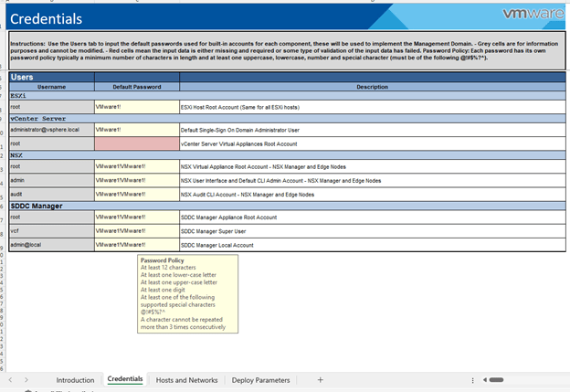
Next, “Credentials” sheet.
Check the password policy and make sure to generate passwords accordingly. It fails at validation if its not meet.
Any unacceptable values cell turns to RED in this entire sheet.
Moving on to next sheet “Hosts and Networks”.
Couple of things to discuss here,
Management Domain Networks – All networks should be pre-created on the TOR.
Here is the screenshot from my TOR.
Management Domain ESXi Hosts – All IP’s to be reserved and DNS records in place.
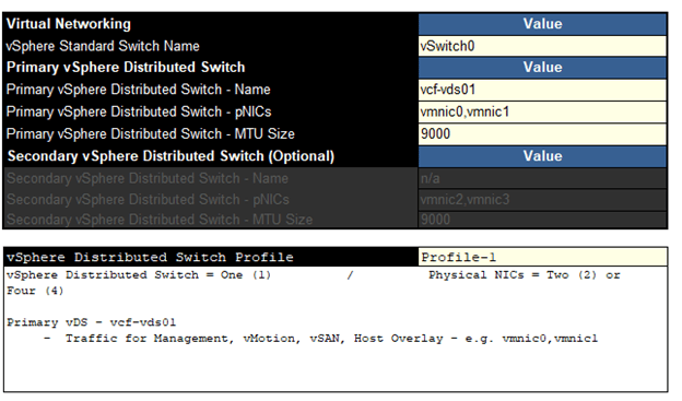
Moving onto “vSphere Distributed Switch Profile” in this sheet. It has 3 profiles. Let’s talk about available options.
Profile-1
This profile will deploy a single vDS with 2 or 4 uplinks. All network traffic will flow through the assigned nics in this vDS.
Profile-2
If you want to split the VSAN traffic on dedicated pnics, choose this option.
This one deploys 2 VDS. You can see that the first vDS will carry management, vMotion, Host Overlay traffic and the other one is for VSAN. Each vDS can have up to 2 pnics.
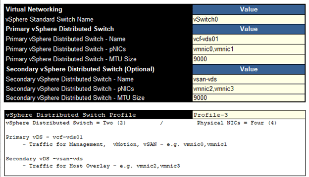
Profile-3
This one also deploys 2 vDS, just that the VSAN traffic is merged into 1stvds and 2nd vds only carries host overlay traffic.
Select the profile as per your business requirement and move to next step. For this lab, I have selected the 1st profile.
Moving to the “NSX Host Overlay Network” – You have an option to enable DHCP on 1634 vlan or define values manually.
Next – “Deploy Parameters” sheet,
Define all parameters here carefully. Again, If something is not good, the cell would turn RED.
As discussed in 1st blog in this series, VCF has now introduced subscription-based licensing. If you select “NO”, then you have to manually enter license keys here. If yes, a note appears in RED,
Just found out that the vmware kb’s are redirecting to Broadcom already. 😊
“During bring-up, in subscription licensing mode, the management domain is deployed in evaluation mode. It is expected that you complete the subscription process for VMware Cloud Foundation+ within 60 days. After the period has expired, you cannot do any actions related the workload domains, such as add or expand workload domain, add or remove cluster, add or remove host”
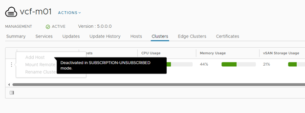
One caveat here, if you deploy the stack in subscription-based model, the SDDC manager does not allow perform any additional operations until you finish the subscription process. In short, it is of no use until you finish the subscription.
Let me show you,
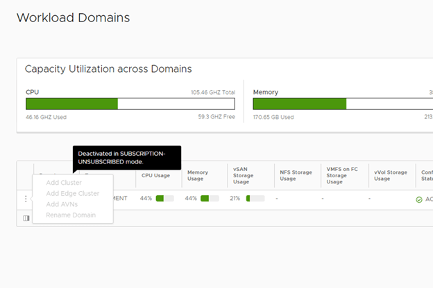
This screenshot was captured when I deployed it subscription model. This is what you see when you deploy it in subscription model and do not activate it,
All additional config options will be grayed out. You see a msg there “Deactivated in Subscription-Unsubscribed mode.”
Any changes to “Workload Domain” will be blocked.
No adding hosts to mgmnt domain,
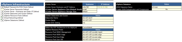
Back to Deploy Parameter, So, make your choices wisely and plan it accordingly. Moving to “vSphere Infra” section in the deployment parameters sheet.
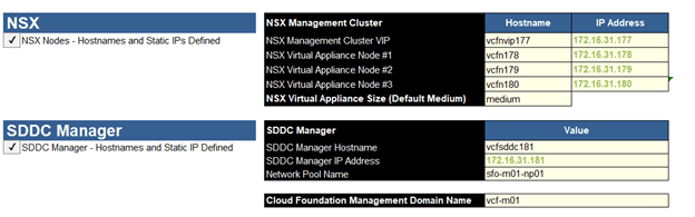
And finally, the NSX & SDDC section,
We are all set to upload this “Deployment Parameter” sheet to Cloud Builder and begin the deployment. That is all for this blog. We will perform the actual deployment in next blog.
Got the VCF 5.X env stood up after few attempts. It was fun and good learning too.
Planning / Design phase plays an important role in VCF deployment. I would say, deployment is just a day task, however, planning goes on for weeks. I would specifically like to emphasize on ‘Licensing’. VCF can be deployed in either subscriptions based licensing model or perpetual. I will discuss about this in later blogs in this series.
Imp Note: You cannot return to using a perpetual license without doing a full bring-up rebuild.
Let’s get into “Preparation” phase and start preparing the infrastructure for VCF deployment.
The deployment of VMware Cloud Foundation is automated. We use VMware Cloud Builder initially to deploy all management domain components. The following components / options have been removed from 5.X initial deployment, compared to previous versions.
All of it can only be configured via SDDC manager after successful deployment. Hence, it has become little easy when it comes to the deployment. Due to the multiple attempts of deployment, I am able to jot down the high-level deployment flow here, which is automated and performed by the Cloud Builder once you start the deployment.
After the validation, CB performs the following step to configure the VCF env.
Connect to 1st target ESXi host and configure single host VSAN datastore. Start the vCenter deployment on 1st VSAN enabled host. After successful deployment of vCenter, Create Datacenter object, Cluster and adds remaining 3 hosts in the cluster. Configure all vmk’s on all 4 hosts. Create VDS and add all 4 hosts to VDS. Configure disk group to form a VSAN datastore on all hosts. Deploy 3 NSX managers on management port group and Configure a VIP. Add Compute Manager (vCenter) and create required transport zones, uplink profiles & network pools. Configure vSphere cluster for NSX (VIBs installation) Deploy SDDC manager. And some post deployments tasks for cleanup. Finish.
And this is what you would expect after the successful deployment. 😊
Believe me, it’s going take multiple attempts if you are doing it for the first time.
Let’s have a look at the Bill of Materials (BOM) for Cloud Foundation version 5.0.0.0 Build 21822418.
Software Component
Version
Cloud Builder VM
5.0-21822418
SDDC Manager
5.0-21822418
VMware vCenter Server Appliance
8.0 U1a -21815093
VMware ESXi
8.0 U1a -21813344
VMware NSX-T Data Center
4.1.0.2.0-21761691
Aria Suite Lifecycle
8.10 Patch 1 -21331275
It’s always a good idea to check release notes of the product before you design & deploy. You can find the release notes here.
Let’s discuss and understand the high level installation flow,
Configure TOR for the networks that are being used by VCF. In our case, we have VyOS router. Deploy a Cloud Builder VM on standalone source physical ESXi. Install and Configure 4 ESXi Servers as per the pre-requisites. Fill in the “Deployment Parameters” excel sheet carefully. Upload “Deployment Parameter” excel sheet to Cloud Builder. Resolve the issues / warning shown on the validation page of CB. Start the deployment. Post deployment, you will have a vCenter, 4 ESXi servers, 3 NSX managers & SDDC manager deployed. Additionally, you can deploy VI workload domain using SDDC manager. This will allow you to deploy Kubernetes cluster and vRealize Suite components.
You definitely need huge amount of compute resources to deploy this solution.
This entire solution was installed on a single physical ESXi server. Following is the configuration of the server.
HP ProLiant DL360 Gen9 2 X Intel(R) Xeon(R) CPU E5-2650 v3 @ 2.30GHz 512 GB Memory 4 TB SSD
Am sure it is possible in 256 gigs of memory too.
Let’s prepare the infra for VCF lab.
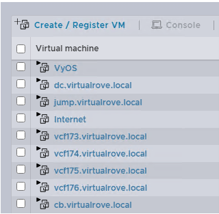
I will call my physical esxi server as a base esxi in this blog. So, here is my base esxi and VM’s installed on it.
VyOS – This virtual router will act as a TOR for VCF env. dc.virtaulrove.local – This is a Domain Controller & DNS Server in the env. jumpbox.virtaulrove.local – To connect to the env. vcf173 to vcf176 – These will be the target ESXi’s for our VCF deployment. cb.virtaulrove.local – Cloud Builder VM to deploy VCF.
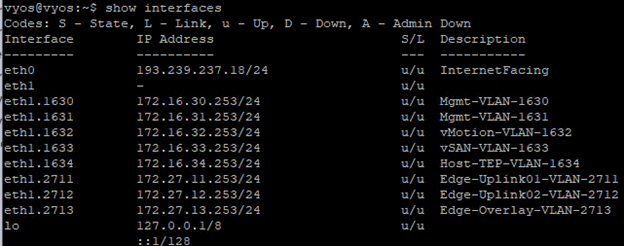
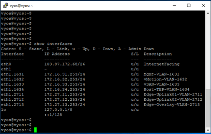
Here is a look at the TOR and interfaces configured…
Network Requirements: Management domain networks to be in place on physical switch (TOR). Jumbo frames (MTU 9000) are recommended on all VLANs or minimum of 1600 MTU.
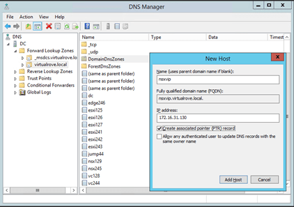
Following DNS records to be in place before we start with the installation.
Cloud Builder Deployment:
Cloud Builder is an appliance provided by VMware to build VCF env on target ESXi’s. It is a one time use VM and can be powered off after the successful deployment of VCF management domain. After the deployment, we will use SDDC manager for managing additional VI domains. I will be deploying this appliance in VLAN 1631, so that it gets access to DC and all our target ESXi servers.
Download the correct CB ova from the downloads,
We also need excel sheet to downloaded from the same page.
‘Cloud Builder Deployment Parameter Guide’
This is a deployment parameter sheet used by CB to deploy VCF infrastructure.
Deployment is straight forward like any other ova deployment. Make sure to you choose right password while deploying the ova. The admin & root password must be a minimum of 8 characters and include at least one uppercase, one lowercase, one digit, and one special character. If this does not meet, then the deployment will fail which results in re-deploying ova.
Nested ESXi Installation & Prereqs With all these things in place, our next step is to deploy 4 nested ESXi servers on our physical ESXi host. These will be our target hosts for VCF deployment. Download the correct supported esxi version ISO from VMware downloads.
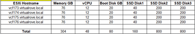
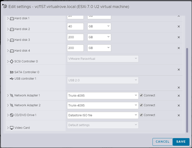
All ESXi should have an identical configuration. I have following configuration in my lab.
And 2 network cards attached to Trunk_4095. This will allow an esxi to communicate with all networks on the TOR.
Map the ISO to CD drive and start the installation.
I am not going to show ESXi installation steps, since it is available online in multiple blogs. Let’s look at the custom settings after the installation.
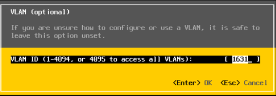
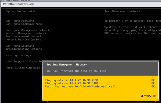
DCUI VLAN settings should be set to 1631.
IPv4 Config
DNS Config
And finally, make sure that the ‘Test Management Network’ on DCUI shows OK for all tests.
Repeat this for all 4 nested esxi.
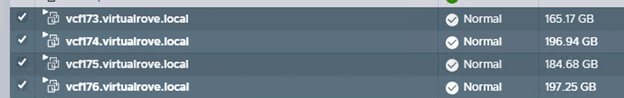
I have all my 4 target esxi severs ready. Let’s look at the ESXi configuration that has to be in place before we can utilize them for VCF deployment.
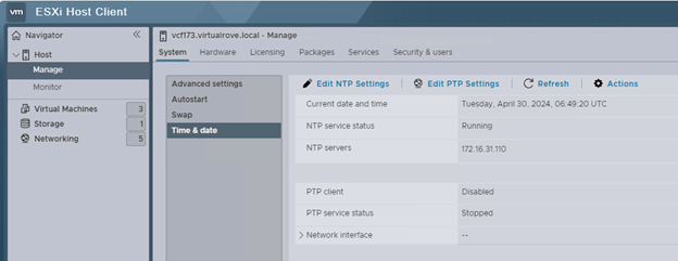
All ESXi must have ‘VM network’ and ‘Management network’ VLAN id 1631 configured. NTP server address configured on all ESXi.
SSH & NTP service to be enabled and policy set to ‘Start & Stop with the host’
All additional disks to be present on an ESXi as a SSD and ready for VSAN configuration. You can check it here.
If your base ESXi has HDD and not SSD, then you can use following command to mark those HDD to SSD.
You can either connect to DC and putty to ESXi or open ESXi console and run these commands.
Once done, run ‘esxcli storage core device list’ command and verify if you see SSD instead of HDD.
Well, that should complete all our pre-requisites for target esxi’s.
Till now, we have completed configuration of Domain controller, VyoS router, 4 nested target ESXi & Cloud Builder ova deployment. Following VM’s have been created on my physical ESXi host.
I will see you in the next post. Will discuss about “Deployment Parameters” excel sheet in detail. Hope that the information in the blog is helpful. Thank you.
Our NSX env is fully functional and we are ready to migrate workload from vCenter VDS to NSX env.
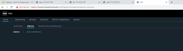
It’s always a good practice to verify the NSX env before we start working on it.
Login to NSX VIP and look for Alarms,
Check the cluster status,
And then look for host transport nodes if they are showing host status as UP,
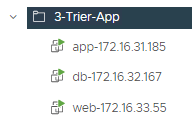
For testing purposes, I have created 3 windows vm’s. All three vm’s connects to 3 different port groups on vCenter VDS. We will move these VM’s from vCenter VDS to NSX managed segments.
Following are test VM’s with their respective vds port groups. I have named these VM’s according to PG.
Next, we need to create Segments in NSX env. A Segment is nothing but the portgroup.
Let’s have a look at the types of Segments.
VLAN Baked Segments: In this type, you will define a VLAN ID for the segments, however you also have to make sure that this vlan configure exists on your physical top of the rack switch.
Overlay Backed Segments: This segment can be configured without any configuration on the physical infrastructure. It gets attached to Overlay Transport Zone and traffic is carried by a tunnel between the hosts.
As stated earlier, we would be only focusing on VLAN backed segments in this blogpost. Visit the following blog if you are looking for overlay backed segment.
Then we move to create a VLAN backed segment in NSX. You can create vlan backed segments for all networks that exist on your TOR (top of the rack switches). For this demo, I will be using Management-1631, vMotion-1632 and VSAN-1633 networks.
In my lab env, following networks are pre-created on the TOR.
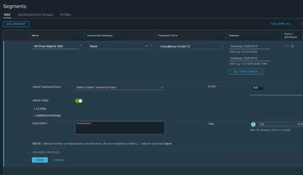
Login to NSX VIP> Networking> Segments> Add Segment
Name: VR-Prod-Mgmnt-1631 Transport Zone: VirtualRove-VLAN-TZ (This is where our esxi host transport nodes are connected) VLAN: 1631
SAVE
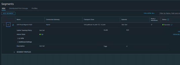
Verify that the Segment status is Success.
Once the segment is created in NSX, go back to vCenter and verify if you see the newly created segment. You will see a letter “N” for all NSX create segments.
Click on the newly created Segment.
Note that the Summary section shows more information about the segment.
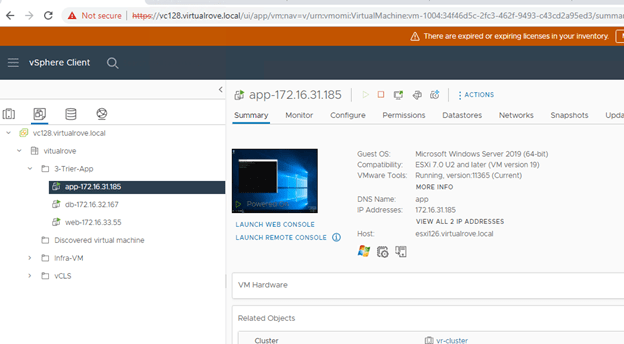
We will now move a VM called “app-172.16.31.185” from VDS to NSX.
Source VDS portgroup is “vDS-Management-1631” Destination NSX Segment is “VR-Prod-Mgmnt-1631”
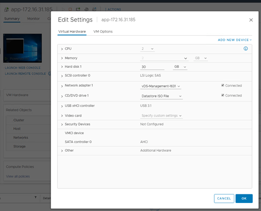
Verify that it is connected to VDS portgroup.
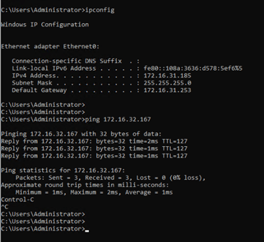
Login to the VM and start a ping to its gateway IP.
Login to the vCenter> Networking view> Right Click the source port group>
And select “Migrate VM’s to another network”.
In the migration wizard, select newly created NSX vlan backed segment in destination network,
Select the VM that needs to be migrated into the NSX env,
Review and Finish,
Monitor the ping command if we see any drops.
All looks good. NO ping drops and I can still ping to the vm ip from other machines in the network.
We have successfully migrated a VM into the NSX env. Verify the network name in VM settings,
Click on the NSX segment in vCenter and verify if you see the VM,
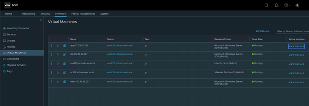
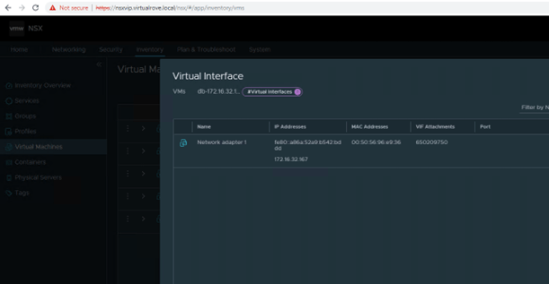
You can also verify the same from NSX side, Login to NSX> Inventory> Virtual Machines> Click on View Details for the VM that we just migrated,
You will see port information in details section,
You will not see port information for db vm, since it has not been migrated yet.
Remaining VM’s have been moved into the NSX env. Ports column shows “1” for all segments.
We see all 3 NSX segments in vCenter networking view,
Simple ping test in cross subnets. From App To DB,
Well, all looks good. Our workload has been successfully migrated into NSX env.
So, what is the use case here…? Why would customer only configure vlan backed segments…? Why No overlay…? Why No T1, T0 and Edge…?
You will surely understand this in my next blog. Stay tuned. 😊 Hope that this blog series has valuable information.
In this blogpost, I will configure the host transport node for NSX. Basically, in this process, NSX vibs are installed on the ESXi node via NSX Manager. They are also referred to as kernel module. You can see the number of installed vibs on esxi by running following command,
Open up a putty session to one of the esxi and run this command,
esxcli software vib list
Filter the one for NSX by running following command,
esxcli software vib list | grep nsx
We don’t see any since we have not configured this host for NSX yet. Let’s revisit this after the NSX installation.
Note: Preparing ESXi host for NSX does not need host reboot.
Before we prep an esxi host for NSX, check the name of VDS, vCenter> Click on ESXi host> Configure> Virtual Switches,
Note the VDS name. We will revisit here after NSX vibs installation.
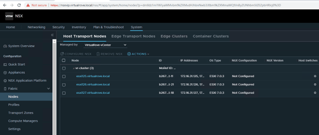
Login to NSX VIP & navigate to System >Nodes >Host Transport Nodes. Change the “Managed by” drop down to vCenter. Notice that the ‘NSX Configuration’ column shows ‘Not Configured’.
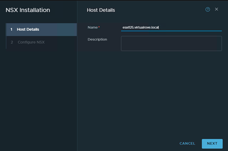
Select the first host & click on ‘Configure NSX’
Next,
Mode: Standard Name: Select appropriate VDS from vCenter Transport Zone: Select VLAN TZ that we created earlier. Uplink Profile: VR-UplinkProf-01
Scroll down to Teaming policy uplink mapping,
Select Uplink1 & Uplink2 respectively.
Here, you are mapping vCenter VDS uplinks to NSX.
Click Finish to begin the installation.
Monitor the progress.
I got an error message here,
Failed to install software on host. Failed to install software on host. esxi127.virtualrove.local : java.rmi.RemoteException: [InstallationError] Failed to create ramdisk stagebootbank: Errors: No space left on device cause = (272, ‘Cannot reserve 272 MB of memory for ramdisk stagebootbank’) Please refer to the log file for more details.
Not sure why this came up. I have enough of compute resources in that cluster. Clicked on “Resolve”
And it was a success. 😊
Next, I see another error.
“The controller has lost connectivity.”
Clicked on “SYNC” here and it was all good.
1st ESXi node has been configured and ready for NSX. Verify the NSX version and node status.
Go back to vCenter> ESXi Host> Configure> Virtual Switches,
We now see the “NSX Switch” added as a prefix to VDS name.
Let’s re-run the command,
esxcli software vib list | grep nsx
We now see all NSX vibs installed on this host.
Let’s move to the next ESXi node and configure it in same way.
All 3 ESXi hosts have been configured for NSX.
That’s all for this post.
I hope that the blog has valuable information. See you all in the next post.
This post will focus on Transport Zones & Uplink Profiles.
It is very important to understand Transport Zones and Uplink Profiles to configure NSX env.
Transport Zone:
All types of hypervisors (that get added to NSX env) as well as EDGE VM are called transport nodes and these transport nodes needs to be a part of transport zones to see particular networks. Collection of transport nodes that define the maximum span for logical switches. A transport zone represents a set of similarly provisioned hypervisors and the logical switches that connect VMs on those hypervisors. It also has been registered with the NSX management plane and has NSX modules installed. For a hypervisor host or NSX Edge to be part of the NSX overlay, it must be added to the NSX transport zone.
There are two types of Transport Zones. Overlay and Vlan Transport Zones. I have already written a blog on previous versions of NSX and explained Transport Zones here…
Let’s get the VLAN backed env in place. It’s simple and easy to understand. Here is the small design that explains what we are trying to accomplish here…
Time to configure VLAN Transport Zone,
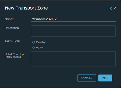
Login to NSX VIP and navigate to System> Transport Zones> ADD Zone
Enter the name and select VLAN under traffic type,
Verify that the TZ is created,
Time to configure Uplink Profile,
An uplink profile defines how you want your network traffic to go outside of NSX env. This helps with the consistent configuration of the network adaptors.
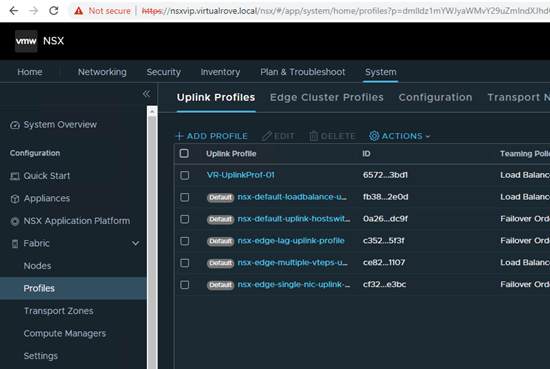
Navigate to System > Fabric> Profiles > Uplink Profile,
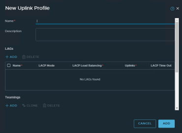
> Add Profile,
Enter the name and description. Leave the LAG’s section for now. I will write another small blog explaining the LAG configuration in NSX env. Scroll down to Teamings,
Select the default policy to “Load Balance Source” Type “U1,U2” in Active Uplink field. Input keywords really does not matter here, you can type any name comma separated. Transport VLAN value to remain 0 in our case.
Teaming Policy Options:
Failover Order: Select an active uplink is specified along with an optional list of standby uplinks. If the active uplink fails, the next uplink in the standby list replaces the active uplink. No actual load balancing is performed with this option.
Load Balance Source: Select a list of active uplinks. When you configure a transport node, you can pin each interface of the transport node to one active uplink. This configuration allows use of several active uplinks at the same time.
A teaming policy defines how C-VDS (Converged VDS) uses its uplink for redundancy and traffic load balancing. Wait, what is C-VDS now…?
N-VDS (NSX Managed VDS): In earlier versions (prior to version 3.0), NSX used to install an additional NSX Managed Distributed Switch. So, one VDS (or VSS) for vSphere traffic and one N-VDS for NSX-T traffic. So, technically speaking, you need 2 more additional pnics for an additional N-VDS switch.
C-VDS (Converged VDS): NSX now uses existing VDS for NSX traffic. However, C-VDS option is only available when you use NSX-T 3 or higher with vSphere 7 along with the VDS version 7.0. You do not need additional pnics in this case.
We are done with the Uplink Profile configuration. More information on Uplink Profiles can be found here,
Check to make sure that the Uplink Profile has been created.
That’s all for this post. We are all set to prepare esxi host transport nodes.I hope that the blog has valuable information. See you all in the next post.
In simple words, vCenter is named as Compute Manager in NSX term.
NSX uses compute resources from the added compute managers to deploy management components. At the same time, it also fetches vSphere cluster information from vCenter / Compute Manager.
Let’s add a compute manager in our env.
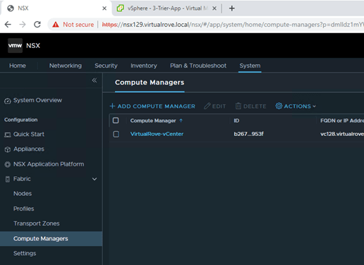
Login to 1st NSX manager and navigate to System > Fabric > Compute Managers >
Click on “Add Compute Manager”.
Fill in the required information here and click on Add.
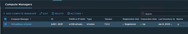
You will be prompted to add the vCenter thumbprint. Click Add and Save. Here is how it will look after adding the compute manager.
Make sure that the compute manager is showing as Registered and its UP.
Important Note:
You can not remove a compute manager if you have successfully prepared ESXi host transport nodes & Edge nodes. You need to manually uninstall NSX from all ESXi host transport nodes and remove any edge nodes as well other components that got deployed from NSX before you try to remove a compute manager.
Next, we add 2 more NSX Managers in the env to form a NSX Cluster.
Why 3 NSX Managers…?
It’s a generic “Cluster” definition in IT world. Each cluster has a Quorum. And NSX Cluster too requires a quorum. Which means, 2 of its 3 members should be up at a given time for NSX env to function / operate properly.
So, 1 NSX Manager is single point of failure. 2 NSX Managers cannot full fill the cluster quorum definition / requirement since generic definition always refers to additional witness node in 2 node cluster configuration. 3 NSX Manager is perfect number to form a cluster.
Hence, 3 NSX Managers, Place them on 3 different physical ESXi nodes and configure anti-affinity to avoid two managers being on single esxi node.
Since it’s a lab env, We will not be deploy remaining 2 appliances. However, here is the link if you want to deploy 2 more appliances.
Next, we configure the VIP (Virtual IP) for NSX Cluster.
What is a VIP…?
A NSX cluster VIP is virtual ip that gets assigned to the cluster. A VIP redirects all requests to master / leader node from the cluster.
When we create a NSX cluster (usually 3 nodes), one of the node gets elected as mater / leader node. Any API and UI request coming in from clients is directed to the leader node. If Leader node is down for any reason, the cluster mechanism automatically elects new leader and all requests gets forward to new leader from the VIP. You also have to make sure that all NSX managers are deployed in the same subnet.
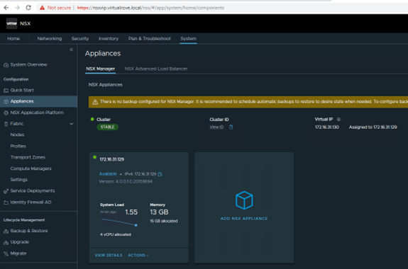
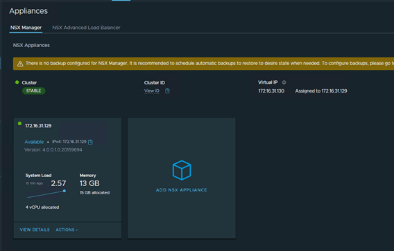
Login to 1st NSX Manager and navigate to System> Appliances…
I only have a single NSX manager in my lab environment. Make sure that the health of the Cluster is “Stable”.
Click on “SET VIRTUAL IP”
Enter the IP address and hit save.
It may take several minutes to add the VIP and NSX GUI might not be accessible for couple of minutes until all required services are up and running.
I see that the VIP has been configured and it is assigned to available NSX manager in the cluster.
I have also created a DNS record for the VIP. Going forward, we will be using this FQDN to access NSX UI.
Let’s login to NSX using VIP and make sure that the state is “Stable”.
All looks good. Let’s move to the next step to prepare Host Transport Nodes for NSX.
That’s all for this post. I hope that the blog has valuable information. See you all in the next post.
Leave your email address in the box below to receive notification on my new blogs.
It’s been a while since I wrote my last blog post. And finally, I found something interesting to write about. Even if this blog starts with NSX installation and configuration, am sure you will definitely find something more interesting as and when I write more. We will be focusing on NSX Security, DFW & Micro-Segmentation in upcoming blogs.
Let’s get started…
First thing first, Release Notes. It’s always good to read release notes for any of the newly launched products. Here is the VMware official link for NSX 4.0…
It’s a major release focusing on NSX networking, security and services. As it mentions in the release notes,
Some of the major enhancements are the following:
IPv6 external-facing Management Plane introduces support for IPv6 communication from external systems with the NSX management cluster (Local Manager only).
Block Malicious IPs in Distributed Firewall is a new capability that allows the ability to block traffic to and from Malicious IPs.
What interests me most are,
Distributed Firewall
Block Malicious IPs in Distributed Firewall is a new capability that allows the ability to block traffic to and from Malicious IPs. This is achieved by ingesting a feed of Malicious IPs provided by VMware Contexa. This feed is automatically updated multiple times a day so that the environment is protected with the latest malicious IPs. For existing environments, the feature will need to be turned on explicitly. For new environments, the feature will be default enabled.
NSX Distributed Firewall has now added support for these following versions for physical servers: RHEL 8.2, 8.4, Ubuntu 20.04, CentOS 8.2, 8.4.
In this series of blogs, I will be focusing on NSX 4.0 env setup and later NSX Networking Security, Distributed firewall, Micro-Segmentation & will also touch base on IDS/IPS.
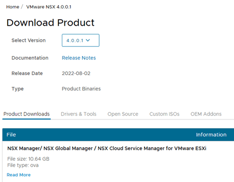
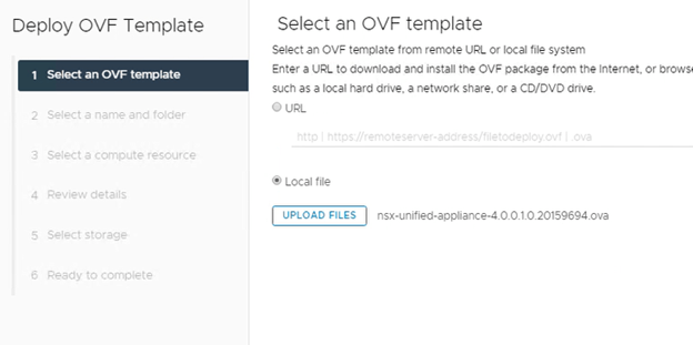
With that let’s get started with NSX 4.0 manager installation. This is pretty simple and straight forward process to deploy NSX manger like previous versions. Download the OVA file from the below link.
Make sure to download the 1st OVA file from the link.
If you do not have access to download the file, you will see following message…
You either are not entitled or do not have permissions to download this product. Check with your My VMware Super User, Procurement Contact or Administrator.
If you recently purchased this product through VMware Store or through a third-party, try downloading later.
Not to worry. Follow this link to get the trial version along with the trial license key…
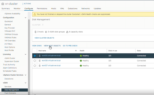
Once you have the downloaded ova file, login to your vCenter and import the ova file. Before we import the ova, let me show you my existing env.
I have one vCenter with 3 VSAN enabled ESXi hosts.
Each host has 3 disks. All disks have been claimed for VSAN cluster.
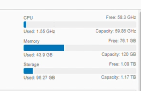
Here is the total compute capacity for this lab,
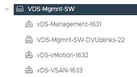
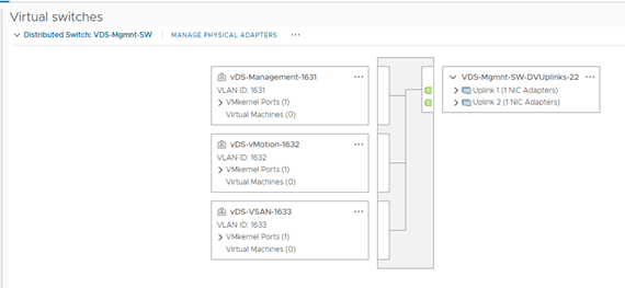
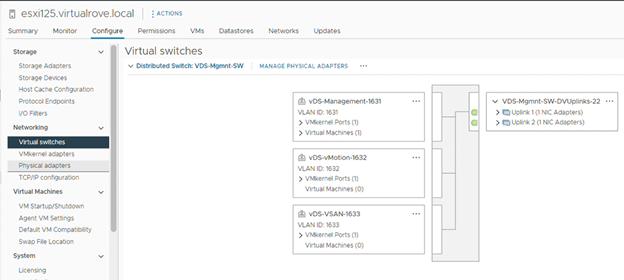
VDS has been configured in the env and it has 2 physical uplinks,
Each host has 3 vmkernel adaptors. Management – VLAN 1631 vMotion – VLAN 1632 VSAN – VLAN 1633
I know that this is basic and anyone looking at the NSX blog will defiantly know this. However, believe me, I have seen networking (physical) background people working on NSX DFW & LB without having complete understanding of base vSphere setup. I have detailed blog on how to configure base vSphere setup here,